
Showing posts with label tricopter. Show all posts
Showing posts with label tricopter. Show all posts
Sunday, April 28, 2013
Tricopter "Mechanical Fuse"
Last Summer, I hastily cut a tricopter frame from carbon fiber + foam laminate. The stock I'd found wasn't large enough to make the whole thing, so I attached the arms with 4-40 nylon cap screws.


Monday, February 18, 2013
borked copter
wicked crash! The carbon fiber foam laminate broke in a place where it had already been weakened by holes.


Thursday, August 30, 2012
Nice Things Tricopter
Up until now, I've made all of my tricopters out of cheap materials like golf club shafts, bamboo, and balsa.
Friday, April 13, 2012
obligatory quadrotor post
I just recently got the chance to play with my first quadrotor. A friend donated to me a small-ish (about 1' square) quad frame made of CF laminated over end grain balsa as well as a handful of older brushless motors and ESCs. I haven't always been the biggest fan of quadrotors, but this one flew into my hands so I figured I'd better try it out.
Sunday, January 29, 2012
carbon fiber tricopter frame
The last tricopter frame was really light. That was about the only good thing about it. The wood was brittle, and broke at the joint of the T a couple of times. It didn't take much to fix, but I wasn't pleased with how fragile it was.

Monday, January 23, 2012
lighter tcopter

 after feeling the difference that only a few grams made in the last flight of tcopter, I'm going to try and make it super light and floaty again. I switched the motors and props over to a balsa frame (still T-style). The balsa has a much bigger cross section, but is still very much lighter than the bamboo I used before. While moving the electronics over, I realized that a lot of the wasted weight is in the shield.
 The shield is a clunky 2mm thick fiberglass board that neatly connects the arduino to the sensors and speed controllers. It keeps things tidy, but it's not worth the weight.
Time to make a new, lighter, more compact shield!

I sketched out the profiles of the components to position them properly. I got rid of the unused pins that were soldered on to the other board, and that pesky LED that just mimics the one built into the arduino.

I'm pleased with the compactness of this setup. It gives only the functionality that tcopter needs without the bulk of the previous setup.

Using a crude balance, I determined that the battery weighs almost as much as the empty frame. Sweet! In an ideal setup, I suppose almost all of the weight would be the battery. I'll have to use the scale at MITERS to get some numbers on this thing, but it sure feels lighter. And while I'm certain the frame has shed a few grams, I'm curious as to how the balsa will hold up to crashes.
Only time will tell.
Monday, January 16, 2012
Tcopter flight testing and more ukulele
After some minor controls hiccups, I got tcopter flying.
Thanks to Annie for filming.
One thing I noticed right away about the flight was that it was less floaty, zippy. It seemed sluggish compared to beforehand. Now, the setup is a bit heavier than last time, but only by maybe thirty grams. Then again, that's about 15% more than last time. Too bad Newton wouldn't let me get away with that.
Each experience I have like this reminds me to KEEP THINGS LIGHT! When they're light, they take less force to move, so they can stay in the air longer. Of course, I could slap on a bigger power system to give it more force to thrash around, but then the frame would have to to be built (heavier) to withstand the extra force.
I'm currently looking into solutions for making a really light frame that can still take some abuse. One trick that I learned from some friends in DBF was to sandwich end-grain balsa wood between sheets of carbon fiber. It makes super light (not much heavier than balsa) and very stiff spars.
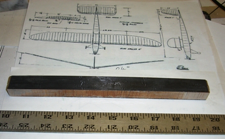 |
| first google result for "end grain balsa spar" |
In other news, I've been having a lot of fun with the ukulele (when it's in tune). The nut is slightly angled, so the distance from it to the first fret is just a bit longer than it should be for the low string. I made a quick fix by sticking a chunk of bamboo under the string shoved up against the nut.
 I'll rip the nut off and re position it later.
Also, I've noticed that some of the drier days make the pegs shrink and slip. I can still tune them, it's just a bit more involved than I'd like. Being that it's IAP, I drew up some plans for machine tuners:

Also, I've noticed that some of the drier days make the pegs shrink and slip. I can still tune them, it's just a bit more involved than I'd like. Being that it's IAP, I drew up some plans for machine tuners:

I planned on using a drywall screw as the worm gear, filing off the unnecessary bits of screw. I was also thinking of cutting the large gear myself.. with a hacksaw. This will have to wait for another long weekend, because I fear it will take many hours.
Before you tell me that I can buy cheap and much nicer machine heads for a few dollars each, just let me say that my stubbornness to buy as little and make as much as possible for this uke has held strong.
Machine tuners will happen.
Wednesday, January 11, 2012
16g HK motor troubleshooting
Well, when I tested it, it just jerked around and got really hot. That was disappointing and a bit frustrating after having spent a really long time winding it. After a bit of interweb browsing, I found the issue. I'd followed the wrong winding pattern. So I used three wires, each one wrapped around three poles, all wound in the same direction. That was cool. The problem was that I didn't respect the start and end points of the winding pattern seen below:
 In the diagram, I accidentally put End A next to start C... or something like that. Luckily it was an easy fix. I just unwound the improperly wound wire and redid it correctly.
Functioning motor functions! Now to get T-copter flying....


Functioning motor functions! Now to get T-copter flying....

Tuesday, January 10, 2012
16 gram HK motor winding

Currently the only thing stopping T-copter from flying is this flukey motor. It arrived with a broken wire, but luckily the break was somewhat exposed and I was able to solder it back together.
I somehow managed to break that connection and another while removing it from the antiquated tricopter frame. d'oh!
Being stubbornly frugal, and having never wound a stator before, I decided to try and rewind it rather than dropping a mere $9 on a new one.
The wonky motor wires on the left are held together with thread and superglue after the first surgery.


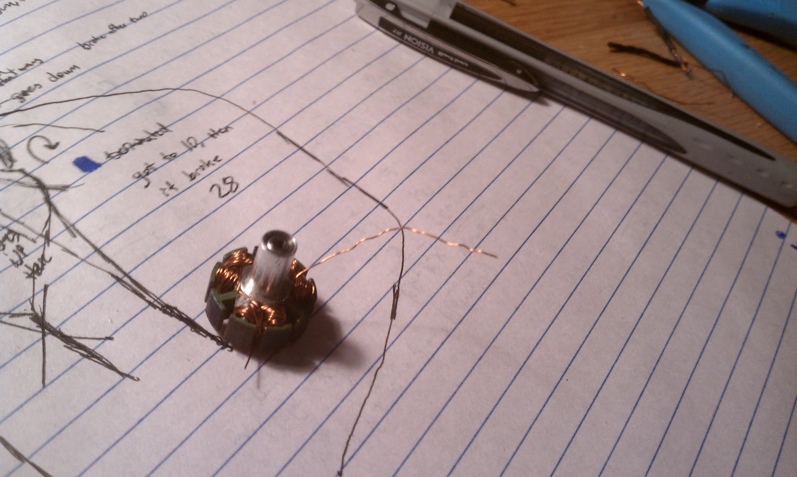

bare stator!

It was at this point when I realized I had very little knowledge of what all of this meant, so I begged Julian for help. He explained that the number of winds plays a part in determining how much torque the motor can produce. More winds means more torque, at the cost of top speed.


This time, I used 30 AWG magnet wire. It seemed a tiny bit thinner than what was originally used, but that should be okay, because it's presumably of higher quality than the shady wire that is used to create nine dollar motors.


A check with the multimeter says there are no shorts, and each of the resistances are the same. With any luck it will work. Testing report to come
Sunday, January 8, 2012
T-copter
Yay more tricopter!
It's taken me a while to realize that a "Y" style frame may not be the best for my tricopter. Because the props are mounted upside-down, there isn't much space left for the battery left underneath the center of the frame. There's enough space, but a triangular frame makes it awkward to mount the battery without extra hardware.
Enter T-copter!

just look at that sexy orthogonality.
This new frame holds the motors in the exact same positions as the last one, but it should give me more "hard points" for mounting things. The battery is attached in the middle of the T, just under the geometric center. It requires only one velcro strap to hold it in place as opposed to the confusing and not-all-that-effective pile of straps and pieces of foam in the last version.
Making the frame
 I cut some more pieces of bamboo from a long (stalk? shoot?) with a flush cut saw and then split them lengthwise and cleaned them up with a knife. MITERS doesn't really stock high tech aerospacey materials like carbon fiber and end grain balsa, but they do have bamboo.

 I tore the old yaw assembly off of the old frame and positioned it on the new one. When it comes to fastening things, I'm a big fan of wrapping and gluing. The shaft that the motor block pivots on is an aluminum rivet. To attach it to the frame, I tack it with a drop or two of CA (superglue), then wrap the two together with some thin and flexible steel wire (the kind they use for hanging pictures). After dousing that with a bit more glue, it gets very strong and stiff.
 After I attached all of the motors, I noticed that the longer beam (the vertical of the 'T') was a bit flexy. I'm probably overbuilding, but I lashed another thin piece of bamboo to the underside of the beam in question. After gluing, megastiffness was restored.
I put all of the electronics on to test (it hadn't been started for a while), but the rear motor wasn't really working. It just jerked around like it had before when one of the windings was broken. Derp. I guess I didn't do a very good job soldering it back together last time.
Anyway, I'll take care of that soon and hopefully get it in the air. I don't expect flight characteristics to change that much. Hopefully not-flight (crash) characteristics will be improved though. :)
It's taken me a while to realize that a "Y" style frame may not be the best for my tricopter. Because the props are mounted upside-down, there isn't much space left for the battery left underneath the center of the frame. There's enough space, but a triangular frame makes it awkward to mount the battery without extra hardware.
Enter T-copter!

just look at that sexy orthogonality.
This new frame holds the motors in the exact same positions as the last one, but it should give me more "hard points" for mounting things. The battery is attached in the middle of the T, just under the geometric center. It requires only one velcro strap to hold it in place as opposed to the confusing and not-all-that-effective pile of straps and pieces of foam in the last version.
Making the frame

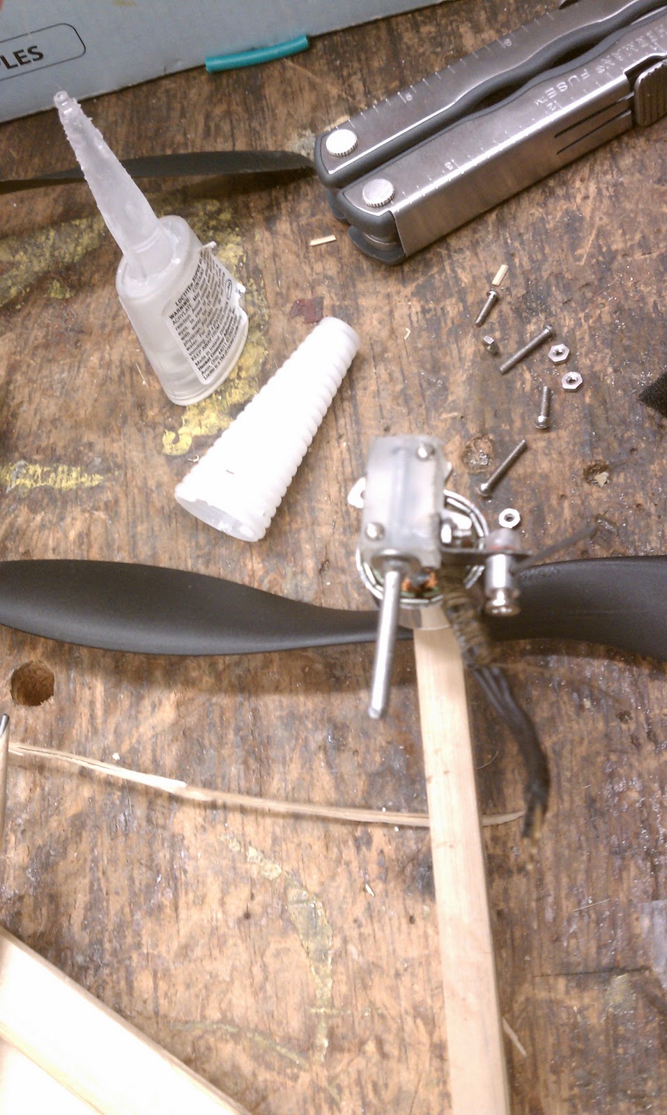


I put all of the electronics on to test (it hadn't been started for a while), but the rear motor wasn't really working. It just jerked around like it had before when one of the windings was broken. Derp. I guess I didn't do a very good job soldering it back together last time.
Anyway, I'll take care of that soon and hopefully get it in the air. I don't expect flight characteristics to change that much. Hopefully not-flight (crash) characteristics will be improved though. :)
Sunday, November 20, 2011
Assembly complete!
With the frame together, I slapped together yaw mechanism. (For yaw to work properly, a tricopter needs to be able to rotate one motor about the axis of its arm). It's sort of tricky to make one that's slop free. The more wobble there is between the servo arm and the movement of the motor, the worse the tricopter will control. I made mine tight by using a delrin-like material for the motor mount. I say delrin-like because the material is just a bit softer than delrin. By drilling it out a bit smaller than the shaft that it rotates around, I get a really solid grip. It moves pretty freely too. The shaft that the motor mount rotates about was then attached to the frame by binding the two with some thin steel wire, then soaking the mess in CA glue. It's solid. The servo was attached similarly.
 The shield containing the arduino and wiimote sensors was mounted on some slivers of the Tempur-Pedic foam. I first tried cutting it with a hot wire which worked okay, but I found that a sharp xacto did a better job. I used small amounts of CA to glue it to the frame and the board. Otherwise, the foam tends to soak up CA and turn into a brick. The board is now nice and squishy. The foam does a really fantastic job of killing vibration.
I tested it by putting the board on my phone (set to vibrate) and taking sensor readings. I then put a sliver of foam under the board, and watched all the wobbles go away.
 Before flying, I had to adjust the PID settings. PID or proportional integral derivative is a type of algorithm used in control systems. It's used in a lot of places, from line following robots to HVAC systems. In my case, P values set the amount of force with which the tricopter resists motion. If P is too small, the tricopter drifts, and if it's too big, it will oscillate (overcompensation for a change in motion creates a runaway feedback loop). The I value takes where the tricopter is, where it should be, and the time that it's been off to determine how to correct itself. This also prevents drifting. The more time the tricopter has not been in the right place, the harder it will work to get there. The D value increases the speed of recovery, but if too high, it can also amplify oscillations.
 I've learned that PID tuning is a fine art, not only is there a PID loop for each axis, but each variable affects the others. It took me almost a day of trial and error to get a nice stable platform. The values I used are to the left.
I'm really pleased with the gyro stabilized flight mode, it feels really solid with the exception of small oscillations after quick maneuvers. I need to look into that. For smooth hovering and basic flight, this setup rocks.
To change settings, all I need to do is upload new values to the Arduino. I do this with an FTDI programmer. One end plugs into six arduino pins, the other into my computer's USB port, then magic happens.

anyway, flight videos soon!

I tested it by putting the board on my phone (set to vibrate) and taking sensor readings. I then put a sliver of foam under the board, and watched all the wobbles go away.

 I've learned that PID tuning is a fine art, not only is there a PID loop for each axis, but each variable affects the others. It took me almost a day of trial and error to get a nice stable platform. The values I used are to the left.
I'm really pleased with the gyro stabilized flight mode, it feels really solid with the exception of small oscillations after quick maneuvers. I need to look into that. For smooth hovering and basic flight, this setup rocks.
To change settings, all I need to do is upload new values to the Arduino. I do this with an FTDI programmer. One end plugs into six arduino pins, the other into my computer's USB port, then magic happens.

anyway, flight videos soon!
Thursday, November 17, 2011
stabilization system assembly
Yikes, it's been a while. I was sort of hosed this week, so this was last weekend's work.
The rest of the electronics arrived yesterday, including a Wiimote and nunchuck.
They obviously didn't want to be disassembled. I quickly encountered the infamous Nintendo "tri wing" screw. Not even the immense tool collection of MITERS had such a screwdriver.

Instead, I drilled them out, absolutely mangling the cute Nintendo peripherals in the process. The sensors intact, I desoldered their proprietary connectors and replaced them with wires.


The thing in the background is an open source piece of java based software used for multiwiicopter configuration. It's pretty straightforward to use, and it lets me know that the board is working. Each of the colored lines represents the magnitude of a gyro or accelerometer reading. It was pretty satisfying to see my motions made into a graph in real time.
Riding an enthusiasm wave, I soldered connectors to my motors and speed controllers. (reversible connectors make it easy to reverse the direction that the motors spin without desoldering anything)


Anyway, I wrote this post while waiting for my batteries to charge so I can start testing functionality, and now they are charged!
Saturday, November 5, 2011
Foam and Frame
I somewhat awkwardly picked up my Tempur-Pedic Sample Kit from the mail today. While I may someday be interested in the purchase of a mattress of theirs, today is not that day. I'd read elsewhere on the internet that the Tempur-Pedic mattress foam makes a fantastic vibration damper, and indeed it seems to.

Last night at MITERS, I slapped together a quick and nasty frame.


Anyway, as soon as my parts get here, I can get a better idea of the scale and proportions of what I'm making. For now it's just prototyping for funsies.
Thursday, November 3, 2011
Pre-CADding
Here's an update on progress. I made a cad model of some sketches I had. I want to get an idea of scale so I can make the necessary tweaks.

Also, some of the components for the control board have arrived. I'm feeding sensor output from Wiimote and a Wii nunchuck boards to an arduino. Pictures when I get my hands on those.

Also, some of the components for the control board have arrived. I'm feeding sensor output from Wiimote and a Wii nunchuck boards to an arduino. Pictures when I get my hands on those.
Sunday, October 23, 2011
Tri-DeathCopter
I got a makership from MITERS! Basically, this means that I get teh monies to help me pay for materials to build something cool. So, what'll it be?
R/C tricopters are fun. They're also pretty hard to fly, and end up being crashed a lot. Crashes break stuff, broken stuff costs money and stops you from flying - general unhappiness. Some folks use complex controllers with lots of sensors and features to keep their multicopters from tipping over. That stuff is expensive, and it probably won't end up teaching the pilot much if it auto-stabilizes and stops itself from crashing into things. So instead of making one of those, I'm going to take the stubborn approach. This tricopter willembrace crashes. be sad to a lesser extent when becoming acquainted with walls at high speed.
For some reason, the wild and wonderful people of MITERS seem to consider sharp spinning things dangerous, and they have dubbed my project the Tri-DeathCopter!
R/C tricopters are fun. They're also pretty hard to fly, and end up being crashed a lot. Crashes break stuff, broken stuff costs money and stops you from flying - general unhappiness. Some folks use complex controllers with lots of sensors and features to keep their multicopters from tipping over. That stuff is expensive, and it probably won't end up teaching the pilot much if it auto-stabilizes and stops itself from crashing into things. So instead of making one of those, I'm going to take the stubborn approach. This tricopter will
For some reason, the wild and wonderful people of MITERS seem to consider sharp spinning things dangerous, and they have dubbed my project the Tri-DeathCopter!
Subscribe to:
Posts (Atom)