I took one of the big project classes in Course II (mechE) this semester, 2.007. 2.007 is Design and Manufacturing I. The class is interesting because it attempts to teach you how to design and build mechanical things, in a semester. That's a pretty ambitious goal, especially given that the class contains about 200 students with varying levels of experience in building stuff. To give students a better chance of learning what they want to learn, 2.007 has a few separate sections. This year, there were three. The standard (and largest) 2.007 section is robotics, in which students build robots to compete in various tasks requiring clever mechanisms, dexterity, and programming skill. The other sections offered in SP2013 were underwater robotics (led by Ed Moriarty and TA'd by djwise, among others), and electric vehicles, dubbed 2.00gokart.
Showing posts with label motor. Show all posts
Showing posts with label motor. Show all posts
Wednesday, May 15, 2013

Sunday, February 17, 2013
wood things, rolling things
I slept a whole lot this IAP. While I wasn't sleeping, I got a few things done.


Friday, November 23, 2012
Stepper Motor Driver
I recently found out that Texas Instruments gives out free samples of some of their ICs. I love free things.
 |
| huh? HTSSOP? |
Wednesday, January 11, 2012
16g HK motor troubleshooting
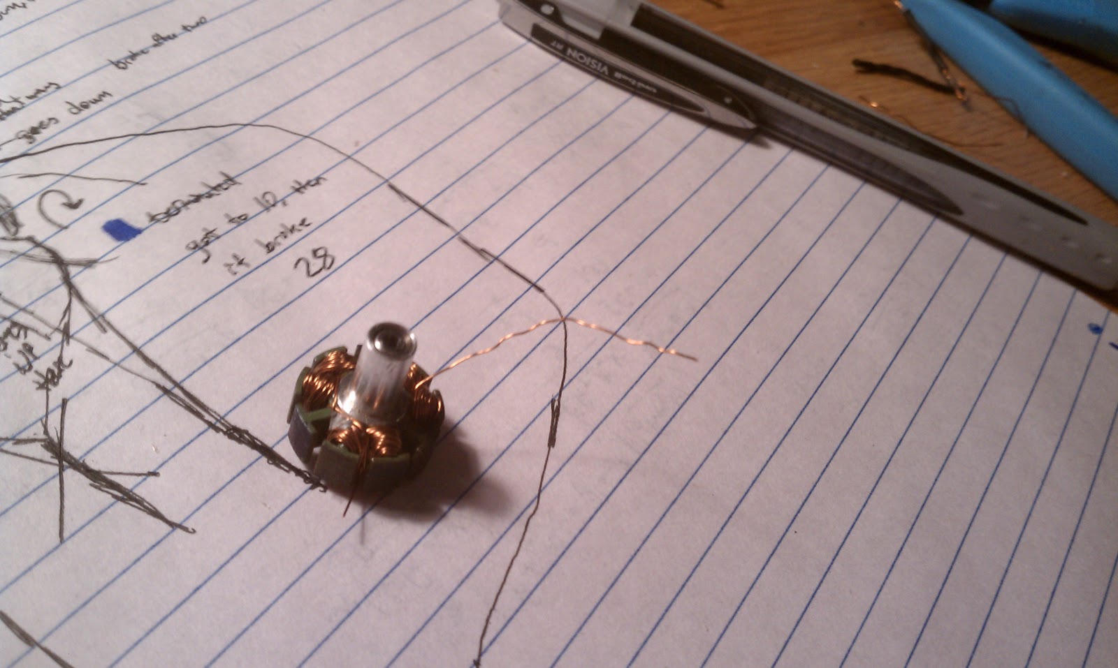
Well, when I tested it, it just jerked around and got really hot. That was disappointing and a bit frustrating after having spent a really long time winding it. After a bit of interweb browsing, I found the issue. I'd followed the wrong winding pattern. So I used three wires, each one wrapped around three poles, all wound in the same direction. That was cool. The problem was that I didn't respect the start and end points of the winding pattern seen below:
 In the diagram, I accidentally put End A next to start C... or something like that. Luckily it was an easy fix. I just unwound the improperly wound wire and redid it correctly.
Functioning motor functions! Now to get T-copter flying....

Functioning motor functions! Now to get T-copter flying....

Tuesday, January 10, 2012
16 gram HK motor winding

Currently the only thing stopping T-copter from flying is this flukey motor. It arrived with a broken wire, but luckily the break was somewhat exposed and I was able to solder it back together.
I somehow managed to break that connection and another while removing it from the antiquated tricopter frame. d'oh!
Being stubbornly frugal, and having never wound a stator before, I decided to try and rewind it rather than dropping a mere $9 on a new one.
The wonky motor wires on the left are held together with thread and superglue after the first surgery.



bare stator!

It was at this point when I realized I had very little knowledge of what all of this meant, so I begged Julian for help. He explained that the number of winds plays a part in determining how much torque the motor can produce. More winds means more torque, at the cost of top speed.


This time, I used 30 AWG magnet wire. It seemed a tiny bit thinner than what was originally used, but that should be okay, because it's presumably of higher quality than the shady wire that is used to create nine dollar motors.


A check with the multimeter says there are no shorts, and each of the resistances are the same. With any luck it will work. Testing report to come
Thursday, November 17, 2011
stabilization system assembly
Yikes, it's been a while. I was sort of hosed this week, so this was last weekend's work.
The rest of the electronics arrived yesterday, including a Wiimote and nunchuck.
They obviously didn't want to be disassembled. I quickly encountered the infamous Nintendo "tri wing" screw. Not even the immense tool collection of MITERS had such a screwdriver.

Instead, I drilled them out, absolutely mangling the cute Nintendo peripherals in the process. The sensors intact, I desoldered their proprietary connectors and replaced them with wires.


The thing in the background is an open source piece of java based software used for multiwiicopter configuration. It's pretty straightforward to use, and it lets me know that the board is working. Each of the colored lines represents the magnitude of a gyro or accelerometer reading. It was pretty satisfying to see my motions made into a graph in real time.
Riding an enthusiasm wave, I soldered connectors to my motors and speed controllers. (reversible connectors make it easy to reverse the direction that the motors spin without desoldering anything)


Anyway, I wrote this post while waiting for my batteries to charge so I can start testing functionality, and now they are charged!
Subscribe to:
Posts (Atom)